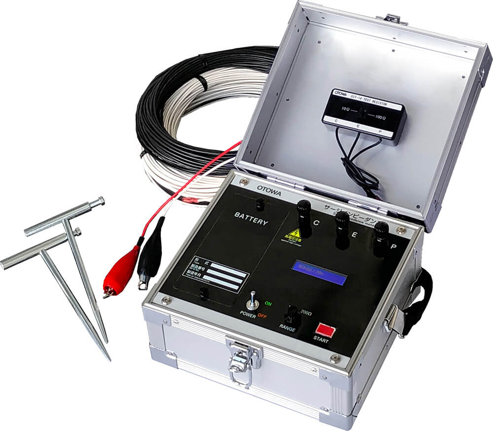
We provide surge impedance measurement services for various types of grounding electrodes. With lightning strikes on the rise, we hope you will make use of this service to reduce the risk of lightning damage.
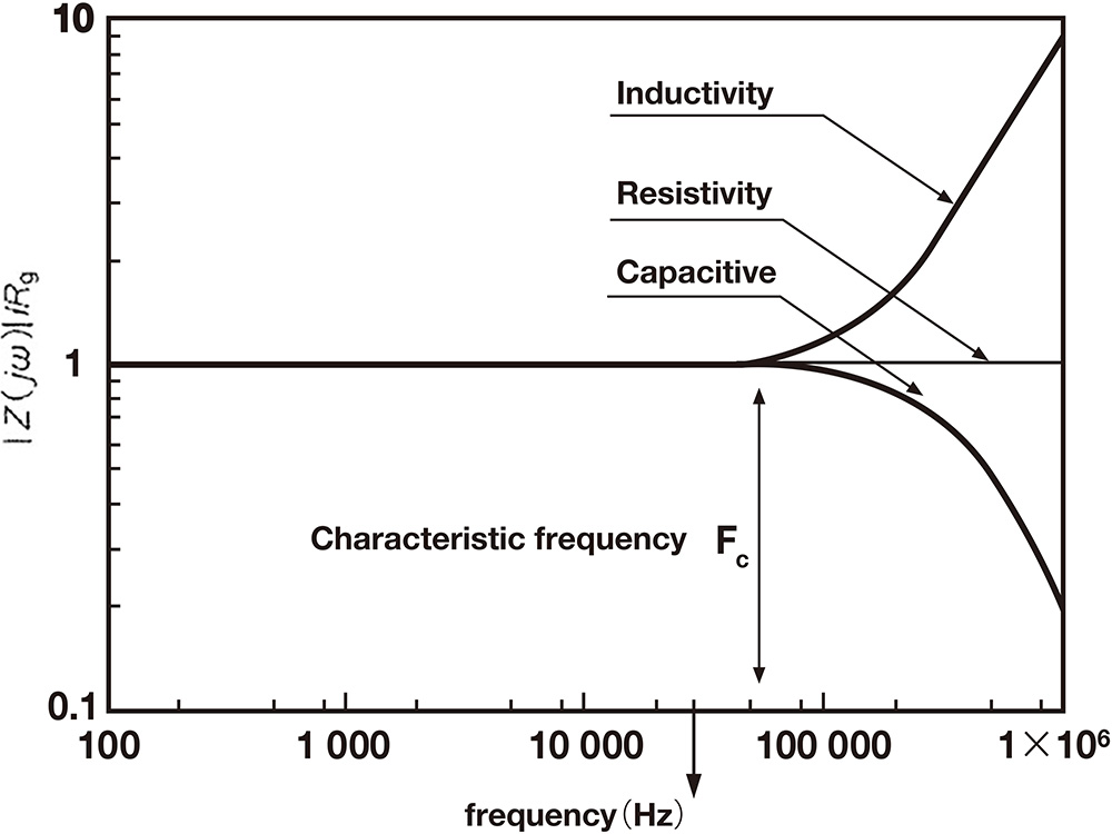
Grounding electrodes for lightning protection have been required to be as low as possible, using the frequency of the commercial power supply (50 Hz, 60 Hz) and the ground resistance value for direct current as management parameters. In recent years, in order to reduce lightning damage, it has become important to lower the impedance, which includes reactance in addition to resistance, as a management parameters for the grounding system including grounding electrodes, in conjunction with the equipotential bonding of the entire facility.
By knowing the surge impedance (Z) of the grounding system to the lightning surge current, it is possible to understand the reverse lightning current of a direct strike lightning current due to an increase in the potential of the grounding electrode, and to construct lightning protection equipment with excellent lightning protection performance using appropriate equipment and at a reasonable cost.
Please feel free to contact us.
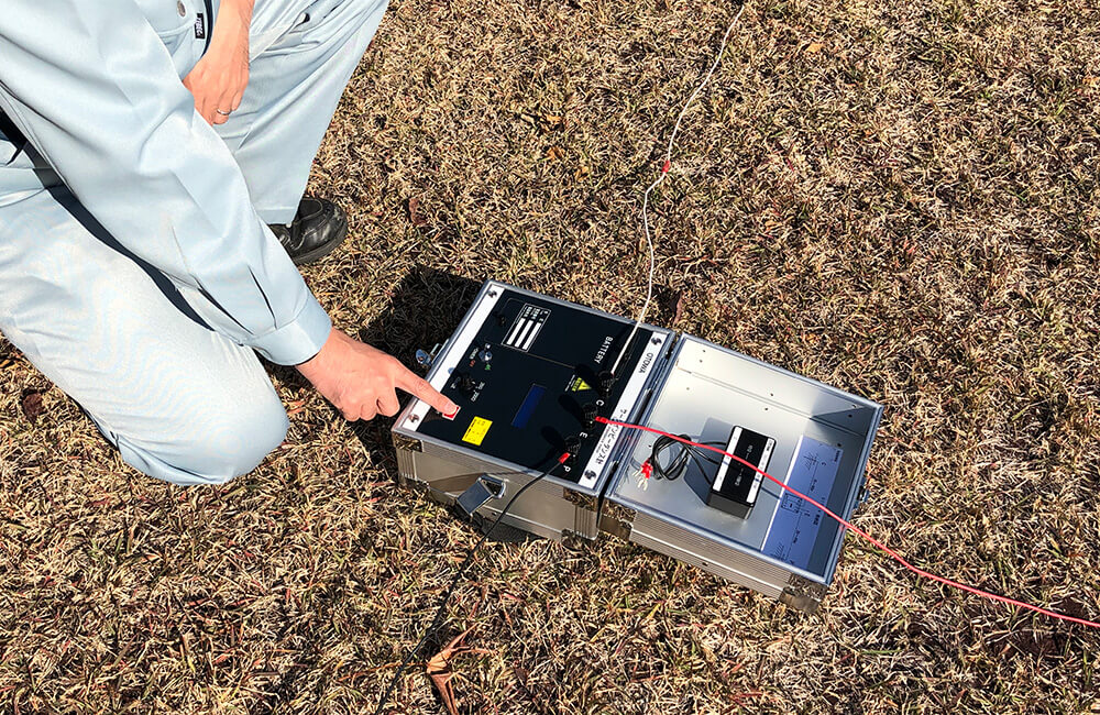
After confirming the measurement environment, we will customize a measurement plan according to the customer's request.
Measurement is carried out with safety as the first priority.
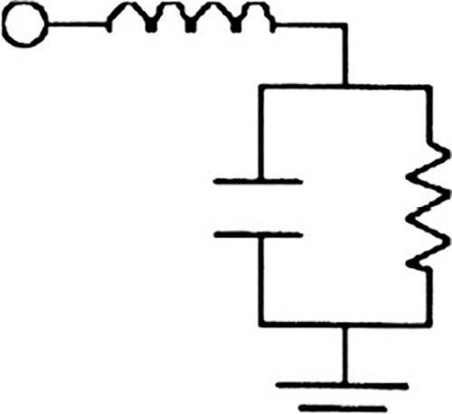
The transient ground resistance value (effective surge impedance) caused by lightning surges, etc. differs from the normal ground resistance value due to the influence of reactance and capacitance contained in the ground.
Measurement with a surge impedance meter is important for grounding electrodes where lightning surge current flow in, such as lightning protection equipment, power transmission towers, and communication antenna tower legs.
The effective surge impedance is the value obtained by dividing the maximum voltage value that appears when a current with front wave length of 1μs flows into the ground by the maximum value of the inflow current.
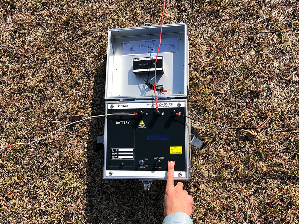
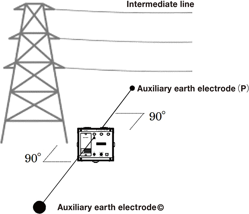
When under power transmission and distribution lines, ground the auxiliary grounding electrodes (C and P) so that they are perpendicular to the power transmission line as much as possible.
