Measure the earth resistivity of the field soil and use it as a parameter for earth design.
Resistivity is defined as the resistance value of the soil per m³.
It is defined as the resistance value of the soil per 1 m³. The symbol is ρ (low) and the unit is Ω-m.
Earth resistivity varies greatly depending on the type of soil, moisture content, temperature, and other factors.
The earth resistivity (ρ) varies with each soil type (location).
The relationship between soil type and ρ is shown in Table 1, but measurement is necessary because there is a large variation even for the same soil type.
| Soil quality | Earth resistivity (Ω-m) |
|---|---|
| Viscosity layer | 0.8~100 |
| Loam layer | 10~500 |
| Sand layer | 100~5,000 |
| Gravel, sand and gravel layer | 100~10,000 |
| Limestone | 60~50,000 |
| Granite | 300~50,000 |
| Lava | 1,000~50,000 |
The earth resistance R (Ω) can be obtained from the following equation.
Since the value of ρ is required to estimate the earth resistance value R, measurement of ρ is essential.
Clarification of earth electrode material procurement (material type, quantity)
Clarification of construction period
Clarification of earth electrode construction costs (Realization of visualization of construction costs)
The Wenner's four-electrode method is used for measurement and analysis.
(From the explanation of JIS A 4201:1992 and JIS T 1022:2018)
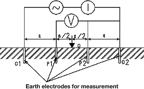
Measurement is performed using current electrodes C1 and C2 and voltage electrodes P1 and P2 as shown in Fig. 1.
Apply current to C1 and C2, and measure the voltage at P1 and P2 to calculate the soil resistance at each depth underground.

Figure 1 : Example of 4-electrode method measurement layout
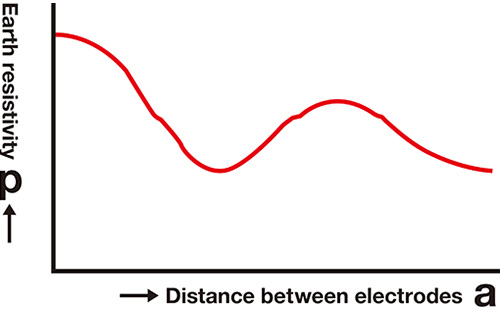
Calculate the apparent earth resistivity ρ and the ρ-a curve in the depth direction (Figure 2).

Figure 2 : ρ-a curve
Determine the earth resistivity ρ for design by calculating the layered depth and earth resistivity ρ for each depth.
Since the analysis is done using the drafting method, experience and expertise are required for accurate calculation.

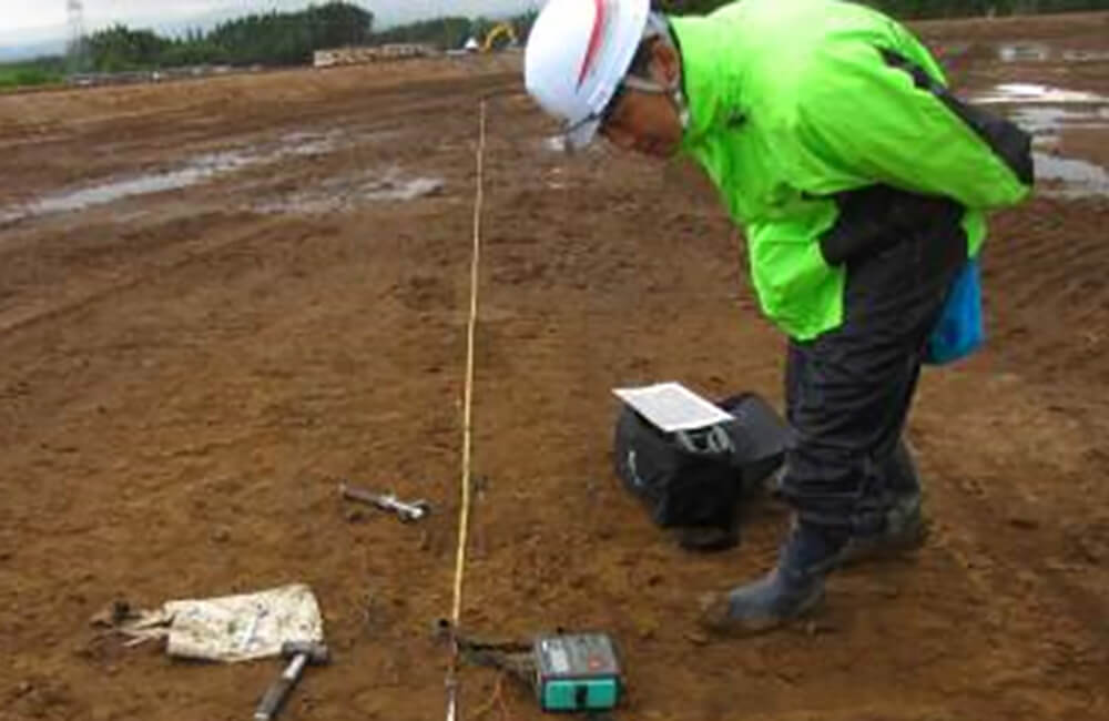
Measurement scenery of earth resistivity measurement